From this zero reference point, two rules apply: and be sure not to over tightenNo Cheater Bars or Sledges! They are not designed for direct attachment to a shaft or coupling that must be rotated to obtain the alignment readings. Consult the job-specific seal drawing regarding the allowed use of lubricant and the type required. This field is for validation purposes and should be left unchanged.
Mixer shaft orbiting, i.e., operating with excessive runout. Determine and record the reading on both dials.11. 0000024191 00000 n
Then fit the Bearing bracket and shaft up against the casing and mark (with bluing pen) the point on shaft or sleeve directly below the seal chamber face. The primary parts of a dial indicator are the face or dial, the case, and the plunger. We use cookies to help provide and enhance our service and tailor content and ads. Jig posts, although useful, can also cause problems if not handled properly. When we align equipment, we are aligning the rotational centerlines of the shafts. Rotate both shafts to 3:00. 6. Standard graph paper is about 10 inches across. Ensure the rim and face dial indicator TIRs are properly determined from the dials prior to performing calculations.2.
Rotate both shafts (if possible) to 3:00.3. Installation of gland to seal chamber not using equal and opposite tightening technique. Ensure that all spare parts taken from inventory are properly issued to trigger reorder. With the coupling broken, mount the fixture to the stationary shaft or coupling hub.2.

Stiffness of the fixture hardware materials Intelligent asset management, asset condition monitoring and reliability in a single conference and expo! This is the case regardless of the Fixturlaser tool you are using.
test Make a vertical line on the extreme left of the horizontal line.
dti 7mm 01mm verdict 0000013885 00000 n
If gross misalignment is not present, and if coupling and/or shaft diameters are large, which is usually the case, accuracy will often be adequate. 0000013689 00000 n

Visually inspect bearing for signs of deterioration.
indicator littlemachineshop dial test compatibility Plot the offset from the rim dial indicator on line DIR. 0000001831 00000 n
Long spans between coupling halves may cause the dial indicator fixture to sag measurably because of the weight of the fixture and the dial indicators. Set the face dial indicator to read zero.3. The cost of this unit is approximately $150. Adjust idler to tighten chain when needed. Maximize the sweep distance of the face dial indicator for the geometry of the machine being aligned.
indicator It occurs due to the measurement surface curvature, as illustrated in Figures 5-15 and 5-16.
During installation, it is critical that these bolts be installed at an elevation that will allow only a few threads (three to four) to protrude above the top of the nut. In most cases the stationary machines center of rotation is the target and reference for all measurements and corrections of the movable machine. To measure angularity using dial indicators, a fixture bracket is attached to one shaft and the dial is set-up to contact the face of the other coupling hub. The simplest way to eliminate the effects of sag is to dial it into the readings at the initial measurement position. 0000001287 00000 n
Rotate the fixtures to the 6:00 position and read the amount of sag. If seal must be installed over damaged shaft surface, assure that seal alignment is correct. Always assure that a clean undamaged shaft surface is available when seal set screws will fasten to the shaft. Remove shaft and Bearing bracket from casing and mark the dimension where the back of the retainer sits when assembled. The dial is then rotated 180 degrees, for example, to the 6:00 position. 4. Proper spring compression check (Working height)Obtain dimension from seal drawing which shows the distance between the back of the seal retainer and the seal chamber face. If the movable shaft is above the horizontal stationary shaft reference line the shaft is too high. 0000024162 00000 n
Precut shims aren't always what they're marked; many shim manufacturers designate shims with the nominal thickness.4. The "A" Dimension should be slightly less than the coupling diameter. straightedge in position C1A5, supports adjusted to 0; straightedge in position A1C5, value of B3 from step 2 aligned and straightedge at the ends aligned to equal distances; the two diagonals define the plane embodiment; measurements A1 and C5 registered; straightedge in position A1C1 aligned to the already registered measured values A1 and C1, B1 measured and registered, etc.
When we move a machine that is mounted in a horizontal position, such as a pump and motor, we reposition the movable machine by moving in only two planes, vertical and horizontal. The other offset point is derived from the face dial indicator (DIF) reading andthe A dimension. The reason is that as the fixtures are rotated from 12:00 to 6:00 while mounted on the machine, the reading given includes a combination of sag and misalignment. Lubricate the O ring with Krytox or equal lubricant. Factors that influence how much sag exists include: As the plunger moves into the case, the needle travels clockwisegiving a POSITIVE reading. If removed components cannot be refurbished get rid of them only after new spare parts are in hand. In addition, certain oils can set-up like adhesives and pull material out of the carbon primary ring faces after start-up, resulting in premature seal failures. Conducting an asset criticality assessment (ACA) is the first step in maintaining the assets properly. During each alignment task, after the indicator(s) have been set up on the machine, it is necessary to determine how much bar sag exists. It is not intended that any disassembly of the camshaft box be made to complete this preventive maintenance step. 0000004264 00000 n
mitutoyo Count the number of squares in the plane of the front and rear feet to determine the position and corrections needed. 0000000896 00000 n
0000023818 00000 n
Insert boroscope into cylinder, and examine cylinder wall, valves and/or ports for abnormal conditions. Span of the indicator bar(s)
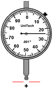
basics plunger moves Set the face dial indicator to zero.4. TIR should be no more than 0.005. Not setting proper spring compression: Excessive compression=more seal wear, Low compressionWill not provide sufficient face contact during start-up and standby conditions allowing excessive leakage. For this reason, the primary seal faces must be free of fingerprints, oil, and/or grease. ScienceDirect is a registered trademark of Elsevier B.V. ScienceDirect is a registered trademark of Elsevier B.V. Machinery Component Maintenance and Repair (Fourth Edition), Long spans between coupling halves may cause the, Practical Machinery Management for Process Plants, Shaft run-out or orbiting is measured by using a, Machinery Component Maintenance and Repair, It is common practice to set up the rim, Pump Mechanical Seal Key Safety and Reliability Issues, Forsthoffer's Proven Guidelines for Rotating Machinery Excellence, Inspection of Geometrical Deviations (Verification), Geometrical Dimensioning and Tolerancing for Design, Manufacturing and Inspection (Third Edition), The procedure for the assessment of the flatness deviation with straightedge and, Major Process Equipment Maintenance and Repair, Visually inspect bushings for signs of deterioration. This movement is transmitted to a pinion, through a series of gears, and on to a hand or pointer that sweeps the dial of the indicator. The dial is set to zero at position #1, for example, 12:00.
dial travel machinist indicator pittsburgh starrett tools Ensure positive offsets are plotted above the horizontal reference line and negative offsets are plotted below the line.5.
#-p Hq=yX:+?d-[${L(-DYN&+hq!G# ePVm:2#F(:mH)RTh0X+2^q~n')l8TbR#!Wc%xI S&;Fwx~>:nC
q#e62F3N2!0x rYf,
9tdH[T,^qvtf
8m'nhE'|M4^wP"|2^g?E#uaF}5prZ>kJqSj?%lUlv1yV3G 2. The face can be rotated so that the needle points to zero. Figure 5-16. Also observe the following rules: To correct vertical misalignment, follow the steps below: 1. Observation of such measurements should be recorded to the nearest 1/16 in. Set both dial indicators to zero.3. As the shaft rotated, the bearing race would wobble axially on the shaft causing the wear. If removed components can be refurbished, immediately initiate procedures for this action. To plot the offsets, perform the following steps: 2. If, however, major misalignment exists, and/or the rim or shaft diameters are small, a significant error is likely to be present. Both of these devices mechanically monitor the bolt elongation during tensioning like a micrometer or dial indicator. If making live vertical corrections, for machines with adjustable chocks, the coupling and foot values are the position of the moveable machine and the arrows show whether to remove or add shims.

Also note any observations in writing for RCFA assistance. Attach the rim dial indicator. Measurement is visual, using a steel scale. Inspect the rotating head assembly as follows: Secondary O ring in pusher sealInspect for discontinuities, confirm proper material and durometer. When interpreting the graph to determine the movable shafts front and rear feet positions in the ertical plane, observe the following rules: 6. It is important to note that indicator bar sag cannot be determined from a reading taken by rotating the shafts. Obtain graph paper with 10 divisions between bold lines.2. Figure 13-53. * This dimension is measured parallel to the shaft.3. Utilize the following steps to correctly install a component mechanical seal: Refer to the Mechanical Seal Drawing and obtain all required mechanical seal components.