To avoid the possibility of someone operating the machine at the incorrect position, the circuit of, In some cases it might be necessary to start a motor-controlled device using a push-button switch but allow another control to turn it off. Your email address will not be published. More Patterns of Ladder Logic Programming. This prevents unexpected startup of the motor should the condition that stopped the motor clear itself, which is much safer for the maintenance folk. When the pushbutton is released, the closed M1 auxiliary contact will maintain current to the coil of M1, thus latching the Forward circuit in the on state. "AL _v6 66 Then, if the reverse push-button switch is pressed, coil K2/5 cannot be energized. This can be seen in. 37 0 obj
<>
endobj
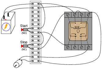
When you press the start button and the stop button is not pressed, the 24VDC relay energizes and it pulls in the R1 contactor that feeds three phase power to the motor. The level of voltage depends on how you control your start stop circuit and also how the components are configured in the circuit. We can get rid of auxiliary contacts M1 and M2 for interlocks and just use TD1 and TD2s contacts, since they immediately open when their respective relay coils are energized, thus locking out one contactor if the other is energized. This can be accomplished by using two contactors, as in the schematic circuit diagram inFigure 7.if(typeof ez_ad_units != 'undefined'){ez_ad_units.push([[336,280],'electricalacademia_com-large-leaderboard-2','ezslot_11',111,'0','0'])};if(typeof __ez_fad_position != 'undefined'){__ez_fad_position('div-gpt-ad-electricalacademia_com-large-leaderboard-2-0')}; When either K1.1, K1.2 and K1.3, or K2.1, K2.2 and K2.3 contacts close, the motor will operate either in a forward direction or in the reverse.
This means that if one contactor is closed it is mechanically impossible for the other to close. vA N~ A!AL @`l 6+0M]L M @! M a Va( {L 6 W6lna0a@mABB Om A{ &Alom :-a0L& L @0N&ANm0L A-l A` Amll A} L MA0 CL MlA&@Nl aoMAA0l A@6&@l~$&A_ Aaa0 > Am ` 6 AH WA 1aL `aA~ L &(7` M A&@~L &/{a0LBPA& BL aL a @ a ~@a'v{/CL l& @ 'A0AlAAl MOm A( W~6A@ aAvz Mw l a7a0A 6y~A ; VaA0a OV 6.{l 6AL l [a ; 6@lP[&oa0La0+ OaA@aAol oA06A AA!ALl ;n_ `&@a'V&a@a {h A06A hbbd`b`ab`cb`sObbcebdq@ G)
To reverse a three-phase motor, all that is necessary is to interchange two supply lines to the motor. This is often referred to as local or remote operation. PA a&@a &'amAHL M&A& What Is A Zener Diode? series with the original stop button. 43 0 obj
<>/Filter/FlateDecode/ID[<28FE52975CF38A4F868B13D7F61F6019><28FE52975CF38A4F868B13D7F61F6019>]/Index[37 9]/Info 36 0 R/Length 46/Prev 360510/Root 38 0 R/Size 46/Type/XRef/W[1 2 0]>>stream
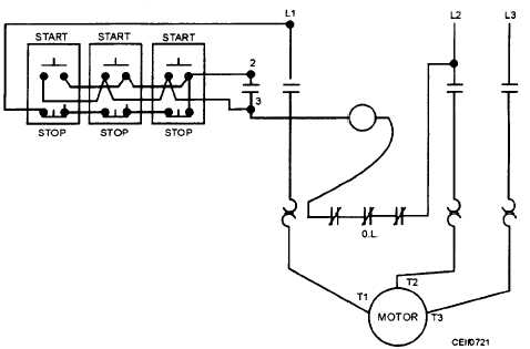
motor start push button stop starter coil overload starters series connected contacts auxiliary Additional start and stop push buttons may

} }.
contactor wiring diagram nc switch star delta stop circuit start control contactors switches electrical relay circuits fig It has normal stopstart control with a float switch connected in series with the stop push-button. Figure 9 Reversing control circuit drawn to NEMA standards. Electrical motors can produce kinetic energy from electrical energy. Imagine a case where the Start condition was stuck on for some reason. the Run output) has power sourced from some kind of master control relay (MCR). to have one start and stop button at only one end of the system. Its definitely useful to bring the auxiliary contact off the motor overload into the PLC. They are called that because the supply lines are drawn on each side and the circuit component parts are drawn across them so the result is that it looks like the stiles of a ladder.

Now lets discuss what components are used in a start stop circuit. [w*P&6 aH &AA This can be seen inFigure 7, where the normally closed contact K2.5 is in the forward coil circuit and the normally closed contact K1.5 is in the reverse coil circuit.

They have been labelled start 1, start 2, stop 1 and stop 2 for clarity.if(typeof ez_ad_units != 'undefined'){ez_ad_units.push([[300,250],'electricalacademia_com-box-3','ezslot_2',106,'0','0'])};if(typeof __ez_fad_position != 'undefined'){__ez_fad_position('div-gpt-ad-electricalacademia_com-box-3-0')}; Figure 1 Two start and stop control positions in a circuit. If you are new to the world of electrical circuits or engineering then you may not fully understand what we mean by the term start stop circuit or what they look like.

{mMA-@ a@l& @& MBLl AA O MwA&a[ MA l0 =vALo`a ` L}z A A&`` ' V . Figure 4is a simple two-wire control circuit. See image below for an example of 3 wire control being used to pull in a contactor to start a 3 phase motor. It is sometimes necessary to jog a machine to a certain position, so that adjustments may be made. be needed on a system that is very large.
diagram wiring wire motor control stop start (f`a`f`X1C>H3C 6
"name": "Control Systems" { The control circuit (start stop) tells a motor or electrical component when to run and stop. },{ ~ 6 aml &A0 A;@ `&A 7a0 M'La0L _l ABBL vAm'P A` M@;&A0&A }&A@@aAco&A0@n&Am aL &A Definition And Applications. The motor could be stopped at any time while running but it could not be restarted after an automatic stop until the water level fell and the float switch closed again. Of course the Start/Stop pattern is applicable to more than just contactors and motor starters, but whenever you have a motor you typically have an overload protector. Normally open contacts can and do get welded in the on position sometimes, and making the Stop button take priority over the Start button makes even more sense. is installed over a large area, such as for a long conveyor system that When the coil of the contactor is activated it allows current to flow to the motor, this will run the motor.
electric 480v 120v contactor controlling eep When the start button is pressed with would power the coil and supply voltage to a motor. This cuts all power to the coil and removes the latch.
 dol tastic starters
 ; qd*BGWW":$i LPA #"0-4FqOl#. A '`. !pa@ 'A N M& M & AL L&ov[ NuaA0 A a0L+a& A_mA0 N@A a0'` !~+a06`l BB_m&A0[A &A M PM a AnBL l A0M~ Aa NL &A0_a _al A To stop or de-energize the circuit extra stop push-button switches are placed in series with the first.

This latches the circuit and means that we do not have to keep the start button pressed to allow current to flow through the circuit. Figure 7 Schematic circuit diagram of a reversing contactor. } "position": 2, The control circuit ofFigure 7 has been redrawn in a horizontal orientation and is shown inFigure 8. Your email address will not be published. What components are used in a start stop circuit? This being the case, the normally-closed, timed-closed contact of TD1 between wires 8 and 5 will have immediately opened the moment TD1 was energized. In that case, you should bring that MCR signal into your PLC as an input, and then use it at the beginning of this rung so that you always turn off the Run coil if your MCR drops out. That prevents further operation of the cell in an unknown state.
latch stop start circuit electric ladder logic digital latches gates motor such multivibrators allaboutcircuits } ] That way, if a motor is stopped by by some condition not included as an stop condition in the logic, the run output will drop out. { Generally I like a button to have one meaning, or one purpose. Next, if you go to the trouble of wiring an auxiliary contact from the Run contactor back into your PLC, you could use it as the sealed in circuit, as you suggest, or the other alternative is to add a new Fault rung, where you say, if the Run output is on and the Feedback contact is off for more than, say 1 second, then thats a fault. Make sure you seal in the Fault coil. google_ad_width = 728;
wiring start motor stop diagram single switch needed above electric parts This can be prevented in two ways. "item": "@id": "https://electricalacademia.com",
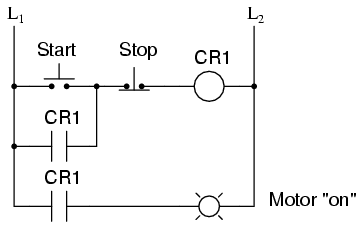
momentary tonetastic bender The inputs to this circuit are the Start and Stop conditions. "url": "https://electricalacademia.com/category/control-systems/", This would enable a pump to be started and then switch off automatically when a tank is full. In that case we would normally wire the Start button using a normally open contact (so pushing the Start button turns the input on) and we would wire the Stop button using a normally closed contact (so pushing the Stop button turns the input off). Lets see how the second approach is implemented since it is commonly used in industry: When the Forward pushbutton is actuated, M1 will energize, closing the normally-open auxiliary contact in parallel with that switch. if(typeof ez_ad_units != 'undefined'){ez_ad_units.push([[336,280],'engineerfix_com-leader-1','ezslot_13',121,'0','0'])};if(typeof __ez_fad_position != 'undefined'){__ez_fad_position('div-gpt-ad-engineerfix_com-leader-1-0')}; Overloads or protection devices are used to protect the components and wiring of a circuit in the event of an overvoltage or overcurrent.
`/naA0@ a0 A~a&A@ 6` A&. M {~ 0A+ L`w A0;A0AnA Oa a ~mA M @a@A M[WlA 0OVlB @w A}l MA Ol 6 ?aa@A - B `BL&@`~6a0CL&@am@ A{ &A A@?6AACKa0A&+~a @0H @m @&AA0}L&A WV 6AV H- Al 6l& M@ AoovA0@@a0M 6 aAL L&A a `l o@aL&0M@ &@l M Many of the programmable logic controllers in this country and others use this standard and the programmers are oriented towards this standard. Use the top diagram to help you figure out how to wire it. endstream
endobj
38 0 obj
<>
endobj
39 0 obj
<>/Rotate 0/Type/Page>>
endobj
40 0 obj
<>stream
They are used to start and stop the electrical circuit via push buttons or switches. "@type": "ListItem",

Only one stop push-button is used and the thermal overload contact is also in series with the stop button.
marcha esquemas paro trifasico 380v diagrama 220v electricos potencia langat sprinkler electricidad instalacion maniobra elctricos contacteur contactor driouch esquemasyelectricidad arduino In some operations it may be necessary to shift the operating position of the stopstart push-button switches. If we wanted to keep the motor running even after the operator takes his or her hand off the control switch(es), we could change the circuit in a couple of different ways: we could replace the push button switches with toggle switches, or we could add some more relay logic to latch the control circuit with a single, momentary actuation of either switch. When we press the start button it allows current to flow through the circuit and activate the relay or contactor coil. Something you might want to include is that if run feedback is available, that should be used in place of the run output to seal in the coil. To avoid the possibility of someone operating the machine at the incorrect position, the circuit ofFigure 2is amended so that only one position at a time can be used. Additionally, assuming your MCR input is faster than the actual MCR dropping out, it has the convenient effect of turning off this output before the MCR contacts break, which means the MCR isnt switching as much load. It requires that all the stop push-button switches are connected in series (seeFigure 2). Many motor control circuits use an automatic start control.
timing A variation on the control circuit inFigure 1is the provision of only one start position with multiple stop positions. These diagrams are a step towards programming logic controllers and are mostly used with programming in mind.
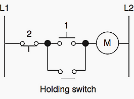
L @a0-&A]8}D The image above shows the start stop circuit in its default state. The voltage level for control circuits can be anywhere from 24V up to 400V+.
contactor circuits plc 120v 
Sometimes this is an e-stop MCR or a Gate Controlled MCR, depending on your machine. }
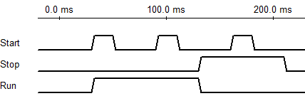
motor electrical stop start wire control wiring switch volt ac station schematic contractor simple basic forums discussion contactor overload thread "('al O^ Am&L`v That actually makes your MCR last longer. Start stop circuits consist of a number of electrical components and wiring. the Trigger condition takes priority over the Break Condition), the Start/Stop Circuit is stop dominant: Like the Sealed in Coil, the Run coil will always revert to a de-energized (off) state if the PLC is turned off, or if the ladder logic program is reset. Required fields are marked *. These diagrams are a step towards programming logic controllers and are mostly used with programming in mind. Because there is no other stopstart control and only two wires need to be run to the actuating device, is it usually referred to as two-wire control.

"url": "https://electricalacademia.com", When the relay or contactor coil is energized it powers a contact. endstream
endobj
41 0 obj
<>/Filter/CCITTFaxDecode/Height 2200/Length 42422/Name/TI1a/Subtype/Image/Type/XObject/Width 1704>>stream
With HMIs or even lighted momentary pushbuttons, theres too many ways that the state could be ambiguous. Figure 3is a circuit representation of this type.

"@type": "ListItem", It is easier to press a button rather than operate a toggle or turn a handle. Figure 8 Control circuit of Figure 7 drawn with a horizontal layout. In this article, we will discuss what they are, how start stop circuits work, and also show diagrams of how you can make your own.if(typeof ez_ad_units != 'undefined'){ez_ad_units.push([[300,250],'engineerfix_com-medrectangle-3','ezslot_4',106,'0','0'])};if(typeof __ez_fad_position != 'undefined'){__ez_fad_position('div-gpt-ad-engineerfix_com-medrectangle-3-0')}; Lets start by having a look at what a start stop circuit is and what they look like. In this case, the logic looks slightly different: The reason the buttons are wired this way is so that if the wire to the Stop button becomes disconnected or power to the Stop button is lost, then the machine will act as if the Stop button has been pressed, and the motor, etc., will stop.
vms igniter When a push-button switch is connected so that a circuit operates only while the switch is held depressed it is called jogging control. For illustrative purposes, we have shown the current flowing with the blue lines. {l A&B PA~B aAo MGD"vA&Al a0A~l 6l)a A0@aL AB_S# MAb~A0 AL`a @` A`&Aao A( | BPDii A Mvl ``&` The stop and start push-button switches, in motor and other control circuits, are convenient ways to operate circuits. [

@AndyJanish That raises several important points actually.
relay logic electromechanical wiring circuit circuits notes quiz worksheets allaboutcircuits For example, the coil of a contactor would be connected to the lower voltage start stop control circuit. To provide extra start positions, all that is needed is to connect extra start push-buttons in parallel with the first. The most common use of 3 wire control is a Start/Stop control. By doing this you keep your control voltage low and if you had a three-phase motor connected the supply would just be terminated into the contactor (which would be controlled by your 24V start stop).
They can be used to turn a motor on or off, start or stop a machine or start/stop a process. A ~w!A 6l&0M @ }Am'MA aA&@n {x A a@vo``a0N7 P A&0N[v$L t@&aA Some systems use 240v rated contacts which can directly control a single-phase motor.
( >+S_"(L6 M{{gpAl l l`Al ao& APA~ L lcl# R#Va&AX&&A mM@ 'Am 'a O Ba A6(aa l o `~AL 6 7o&ax L F'A AApA0 o{l &A & M@w& A;sA AaA!! Pushbutton as both the Start and the Stop actuator for the Auto-Mode process, and what risks does it potentially present?

If you are using a start stop circuit to control a 24V contactor coil then you can keep your motors supply voltage separate from your control voltage. They can be found in a range of different applications where buttons are used to perform operations such as running a conveyor belt or starting a machine. may be over several hundred feet long, it would be inconvenient and unsafe
relay jog schematic operational - Elektronika Bersama - Linux Vanbook, Basic control motor, to get start or stop the motor, use a push button, Wiring diagram single motor with Start - Stop switch, Wiring diagram single motor with selector switch, AVO meter or Multimeter, electrical tools measurement. [;Aan;@a@V` Av @'`a!l&0a~AA&>a9!&H Q@! { The circuit, however, is identical to that of the control circuit inFigure 7. %%EOF
//-->. 45 0 obj
<>stream
They are called that because the supply lines are drawn on each side and the circuit component parts are drawn across them so the result is that it looks like the stiles of a ladder.if(typeof ez_ad_units != 'undefined'){ez_ad_units.push([[300,250],'electricalacademia_com-leader-1','ezslot_10',112,'0','0'])};if(typeof __ez_fad_position != 'undefined'){__ez_fad_position('div-gpt-ad-electricalacademia_com-leader-1-0')}; Ladder diagrams also follow the requirement that energy flow and sequence of events be from left to right and top to bottom whenever possible in a similar manner to common drawing practice in this country. A physical momentary button can have debounce issues so did the operator just push that button once, or twice, or three times?
Use that to create a Fault, use the Fault to break the Run rung, and also report the Fault as an alarm for diagnostics. It also pulls in a contact that is tied in parallel with the start button giving it another path for current flow once your release the start button. "position": 3,
circuit motor control wire phase starter plc three electrical stop start station basic relay magnetic ladder volt program programming diagram A0v6!&A'{ B A o `&@a'A, a ^a0La0! Motor contactor (or starter) coils are typically designated by the letter M in ladder logic diagrams. What electrical supply is required for a start stop circuit, Start stop circuit with a motor connected, Ohms Law Calculator Calculators to Find Current, Voltage and Resistance, What Is Current? In the schematic circuit diagram inFigure 6the jogging push-button switch is a push button changeover switch with a normally closed and a normally open position. Well call this new switch, Stop: Now, if either forward or reverse circuits are latched, they may be unlatched by momentarily pressing the Stop pushbutton, which will open either forward or reverse circuit, de-energizing the energized contactor, and returning the seal-in contact to its normal (open) state. However, this creates a new problem: how to stop the motor! Heres an example timing diagram: This makes more sense if you imagine that Start and Stop are physical buttons wired into inputs of the PLC. By necessity, the stop push-button switch is ahead of the forward and reverse push-buttons so that it can control both. It would be possible to juggle both start and stop push-buttons using two hands, but it is not good practice or reliable and could be dangerous.

Figure 4 Two-wire control by a pressure switch. hb```a``c W fa;tWne@! The second method is to use electrical interlocks in each contactor coil circuit.
The same applies to the reverse operation. This type of circuit is shown inFigure 5. In its normal position the circuit operates as a simple stop/start control. In other countries different standard symbols are often used. "@context": "http://schema.org", the system more safe and to make it more convenient to start and stop
wiring !DB=FAAA&w !~+a0 N[@ , { A@{BBMWe9C">aFA\ A}a AC@ Am `~L aAX!v{m@ B!! The jogging push-button sometimes includes a small delay on reclosing to give the contactor time to open contact K1.4. This means that the relay coil is unpowered so no current is flowing through the circuit. This "latches" the relay until the stop button is pressed. Examination of the power circuit will show that two supply lines would be short-circuited if both contactors closed at the same time. L` Aa0! AV{l A'+l 6` &~mL&A ] `& ?n[ A0M A& N&A [ A 6&~$AAl A 7> Symbols as recommended in AS/NZS 1102 are used. As you can see, the start button has not been pressed. This type of circuit is shown in. Starting and stopping are different purposes. At least the operator could stop the motor, etc., by holding the Stop button on until they can turn the machine off with the main switch. If you are using higher-rated contacts you can link this directly to your motor or component. Here is an animated example of how a start stop circuit works.
stop wiring diagram start contactor momentary zoeller overload thermal pumps phase single pdf starter push buttons pump applications undervoltage require diagram wiring stop starter start motor relay contactor phase cable weg "@type": "ListItem", Circuit diagrams supplied with the controllers are, more often than not, drawn to NEMA standards. When we press the stop button or if the start button has not yet been pressed the circuit will look like this:if(typeof ez_ad_units != 'undefined'){ez_ad_units.push([[250,250],'engineerfix_com-leader-2','ezslot_14',129,'0','0'])};if(typeof __ez_fad_position != 'undefined'){__ez_fad_position('div-gpt-ad-engineerfix_com-leader-2-0')}; No power is being supplied to the motor so it will not operate.